Systems, Sensors & Sampling Equipment
On this page: Communication | Imaging | Illumination | Manipulators | Navigation | Propulsion | Science Workspace | Sensors | Obstacle-Avoidance Sonar | Trim | Variable Ballast | Sampling Equipment |
Communication
Alvin maintains frequent communication with the support ship during each dive and at all operating depths.
Alvin's UQC underwater telephone, which is compatible with Navy systems, can be used for both voice and code communications with Atlantis. An identical unit on Atlantis can interrogate the submersible for ranges, and Alvin may interrogate the support ship as well. Since Alvin has both "up-" and "down-looking" transducers, the UQC may be used to echo range to the bottom to determine altitude, or to the surface to determine depth.
Read more
A VHF radio with all marine channels is used for communication when Alvin is on the surface. An all-channel portable VHF marine radio is carried as a backup and Atlantis is equipped with a marine VHF radio direction finder. The direction finder receives only marine VHF frequencies; users of VHF beacons should confirm reception capability before planning use of the direction finding equipment.
Imaging
One of the biggest advantages of using a human-occupied vehicle for science is having the ability to take in the context of the environment firsthand -- to be able to see areas of concentration and sampling within the larger environment. The addition of two pan & tilt-mounted 4K ultra-high definition cameras along with a real-time 4K and proxy (h.264) video recording system enables closer, more detailed observation and post dive analysis along with improved subsequent dive planning.
Read more
Alvin's imaging system provides native support for twelve SDI video cameras (up to 12G-SDI), up to four HD IP cameras, and four independent pan & tilts. Note: analog cameras are no longer natively supported.
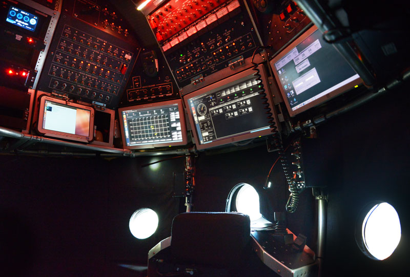
An iPad imaging system user interface provides camera and pan & tilt controls, real time video monitoring, recorder control with active recording tally light, still image capture, and real time navigation and temperature sensor data display.
Cameras and Lighting
- Primary lightning array
- DSP&L Sealite Sphere 200 Series
- Wide angle HD (1080p30) on pan & tilt (6500m)
- Wide angle HD (1080p30) fixed mount (6500m)
- 4K UHD (2160p29.97) on pan & tilt (6500m)
- GoPro Hero11 with DSPL Optim housing & integrated 5.4mm non-distortion lens (6500m)
Cameras
Two pan & tilt-mounted Deep Sea Power & Light Optim SeaCam 4K UHD 6,500m-rated cameras are located below the light bar on the port and starboard brow. The Optim features a 15.5x/12x optical/digital zoom (240x combined), a 78°H x 48°V FOV (in water), and a 350mm minimum object distance at full telephoto that makes for stunning close-up images and brings out the smallest details. The in-hull iPad user interface provides pan & tilt joystick and camera controls for focus (near/far and auto/manual), exposure mode (auto, manual, shutter priority and aperture (iris) priority), shutter speed, F-stop (iris), ISO (gain), white balance (pilot controlled), and zoom (tele/wide).
Read more
For shallow dives (<4,500m), two Kongsberg OE14-522 pan/tilt/zoom HD cameras may be located just above and slightly outboard of the forward-facing port and starboard observer viewports. The OE14-522 is a high quality, high definition underwater video camera with a 10x optical zoom lens mounted on a movable platform inside the view port, giving pan and tilt functionality with no external moving parts. The in-hull iPad user interface provides pan & tilt joystick and camera controls for focus (near/far and auto/manual), exposure mode (auto, manual, shutter priority and aperture (iris) priority), shutter speed, F-stop (iris), ISO (gain), white balance (pilot controlled), and zoom (tele/wide). By default, the speed of the pan and tilt is coupled to the zoom position, i.e., when the lens is at the telephoto position the movements are slow; when in the wide position, the movements are quicker.
Four 6,500m-rated, fixed lens, Deep Sea Power & Light HD Multi SeaCam (domed optics) situational cameras are also installed: one aft looking, one down looking, one on the brow center below the light bar providing a wide field of view of the forward work area, and one dedicated for pilot use installed on a micro pan & tilt above the light bar.
Additionally, Alvin has fixed focus GoPro cameras.
- "BrowGoPro" - Mounted on the brow collecting still imagery every 5 seconds at 23 MP for the duration of the dive (6500m).
- GoPro- As requested by science, with mount points on the manipulator arm, basket or elevator, collecting still or video imagery for the duration of the dive (4500m).
Video Monitors
Along with the video monitoring provided by the iPad web browser user interface, Alvin also includes two Video Assist 7" 12G flat panel displays for in-hull viewing (one for each observer). The displays (1920 x 1200 pixels) are super bright 2500nit HDR monitors that support 3D LUTs and feature professional scopes along with powerful focus assist and exposure tools that help observers accurately set focus, exposure and frame shots.
Video Recording
ProRes LT Encoded Video Data
Port and starboard video recorders are used to record and store ProRes LT 422 encoded video data (other encoder formats are available). Each recorder has a total storage capacity of 4TB split over two 2TB solid state drives (SSDs). The ProRes recorders feature a 12G-SDI connection and support recording SD, HD and Ultra HD (4K) formats up to 2160p60. All recorded ProRes video contains embedded timecode that is synchronized to the in-sphere NTP time server.
Read more
Proxy H.264 Encoded Video Data
Port and starboard proxy video recorders are used to record and store the H.264 encoded 1080p30 proxy video. Each proxy recorder has a minimum total storage capacity of 256GB split over two 128GB SD cards. All recorded proxy video contains embedded timecode that is synchronized to the in-sphere NTP time server.
Additionally the in-sphere imaging server's real-time processing engine generates copies of the port and starboard proxy video data, captures real time navigation metadata, and embeds the metadata in a series of subtitle files for each of the proxy video files. The subtitle files contain dive details as well as an assortment of time stamped navigation data.
Illumination
Alvin has twelve independent lighting channels, each 10A, fused at 80A total.
Multiple 10,000 lumen DSP&L SeaLite Sphere 7200 LED lights can be mounted around the sub to illuminate the work area, with one down-looking at the aft end of the sub. At least four lights mount around the basket and swing arm, with others mounted on the light bar on Alvin's brow. Lighting can be configured as needed based on dive objectives. Constant current drivers allow flicker free operation, and they are fully dimmable via a GUI on the computer inside the sub. We have two optional green LED lights on the light bar, which increase visibility at distance.
Read more
The Optim 4K pan and tilt-mounted cameras can each carry a pair of parallel lasers which can be used to help determine range, size or area of interest of targets observed on the associated camera. The beams are 10 cm apart.
Manipulators
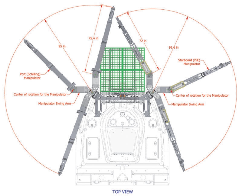
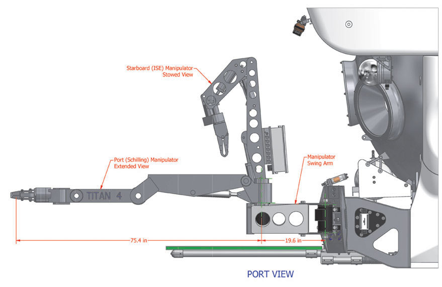
Alvin is fitted with two hydraulically powered manipulators on swing arms to increase reach.
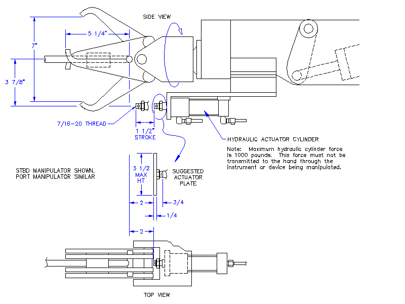
The starboard ISE manipulator has six degrees of movement: shoulder pitch and yaw, elbow pitch, wrist pitch and rotate, and jaw open and close. The manipulator has a maximum extension of 72 inches and a lift capacity of 100 pounds at maximum extension. Remote operation is controlled by a switch panel in the personnel sphere. The arm may be viewed from either the front or starboard side viewports during operation and can be fitted with a hydraulic actuator that can be used as a trigger mechanism to operate devices held by the jaw.
Read more
The port Schilling Titan 4 manipulator has the same six degrees of movement with the additional capability of wrist yaw. Maximum extension is 75 inches, with a fully extended lift capacity of 150 pounds. Wrist torque is rated at 30 ft/lbs and has a maximum rotational speed of 65 RPM. This arm is controlled by a position feedback master/slave mechanism, with the spatially correspondent master located in the personnel sphere allowing viewing and control through the front and port side viewports. This manipulator can also be fitted with an auxiliary hydraulic ram to trigger special equipment. A second Titan 4 can be mounted on the starboard side in place of the ISE manipulator.
Navigation
Alvin's primary navigation sensors are the Doppler velocity log (DVL) used in conjunction with the fiber optic gyroscope (FOG) and disciplined with ultra-short baseline (USBL) fixes. Software integrates DVL information with data from all the other sensors on the sub and calculates the sub's position and distributes the information to the Pilot in real time. The Pilot can then dial in what the the sub should do: maintain position over a certain spot to collect a sample (even in a strong current), hold a specified altitude or depth and 'hover' there, or follow a course or heading. "Step" moves are also possible, where the Pilot enters a shift of a desired amount and the vehicle complies. The scientist could say, 'I want to spin in one spot', and the Pilot could command the sub computers to make it happen.
Propulsion
Alvin's propulsion system provides precise maneuvering in three axes (X, Y, Z) and is accomplished through the use of seven electrically powered, ducted thrusters and an advanced control system. Thrusters are located as follows:
- Three mounted at the stern provide forward/reverse thrust
- Two mounted amidships provide vertical thrust
- Two mounted horizontally, one at the stern & one forward of the sail, provide lateral thrust for side-to-side motion ("crabbing") and rotational motion to turn about the sub's vertical axis
Read more
Alvin's primary positional control is an advanced digital system that incorporates a variety of input devices. Typically the Pilot uses three joysticks that provide proportional control of the sub's motion in the three directions (X,Y,Z).
Alternate control is provided by a potentiometer/switch panel that allows scalar control along the three axes. Additionally, the system includes a number of propulsion modes including: auto heading, auto altitude, auto depth, auto X/Y, and "Stick Lock". Selection of the various modes is available on the Command and Control touch screen and via dedicated push-button switches on the Pilot's panel. The various modes and input methods may be utilized together to provide excellent maneuverability, including precise station keeping in the X,Y and Z axes and command of the sub in incremental steps along each of the axes.
The sub's command architecture includes a variety of inherent redundancies to accommodate minor issues with the propulsion system and prevent significant impact on dive objectives.
Science Workspace
Sampling tools are typically mounted to Alvin's science 'basket', a robust and versatile platform located at the front of the vehicle, between the manipulators, and visible to all three occupants. The basket provides a 400-pound payload capability on 16 square feet (48" x 48") of usable space for sample collecting, science tools, and specialized equipment. The basket frame provides many mounting options and can be routinely reconfigured to meet the specific objectives of each dive. The majority of basket preparation and configuration activity typically takes place the evening before a dive; minor adjustments and final preparation of sensitive experiments happen early in the morning prior to the dive.
Read more
The science basket assembly is designed to be jettisonable in an emergency, so any instruments on the basket which require hydraulic or electrical power must be fed through a release mechanism supplied by the Alvin Group. Payload is attached to the basket with standard fasteners, and when possible should be designed with mounting flanges on the bottom that can accept ¼"-20 hardware.
The basket design is modular, and it can be modified for special uses. The Alvin Group can also design and construct custom baskets or workspaces to accomplish cruise objectives.
Sensors
Doppler Velocity Log
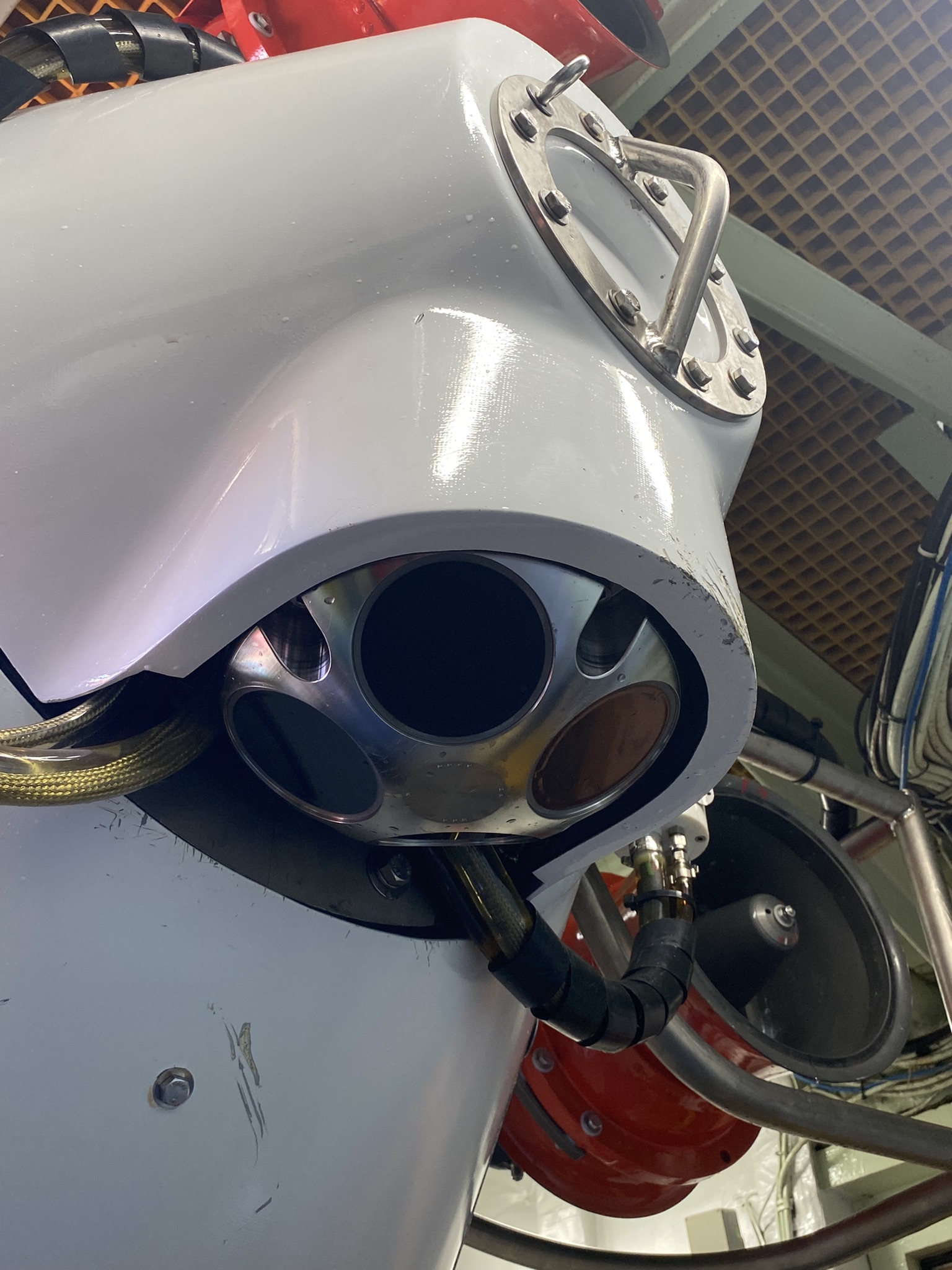
Alvin utilizes a Doppler Velocity Log (DVL) as a means to accurately measure the vehicle's position and motion relative to the seafloor. Currently the submersible utilizes an RDI Teledyne Workhorse Navigator operating at an acoustic frequency of 600 KHz.
The DVL provides data at a high sample rate that includes position, velocity, heading (via a flux-gate magnetic compass), vehicle altitude (up to 90 meters above the seafloor), and vehicle attitude (pitch/roll).
Read more
When Alvin is near the bottom (<90 meters altitude) the unit achieves "bottom lock" to accurately track the vehicle as it moves along the seafloor. During descent and then again on ascent, the unit achieves "water lock" to track the vehicle as it transits through the water column.
Note that DVL-provided heading and attitude are used by the navigation system to calculate the vehicle's position and motion. Primary vehicle heading and attitude are provided by the fiber optic gyro (see below). Both gyro and DVL heading as well as DVL altitude are displayed as a part of the Pilot's command and control touchscreen interface. Other DVL data is available as a part of the vehicle's output data set and viewable real time on the "Sensors" page of the command and control software.
Sensor accuracy is as follows:
| Velocity: | +/- 0.1 cm/s (+/- 0.2 %) |
| Flux-gate compass (Heading): | +/- 2.0 degrees |
| Attitude (Pitch/Roll): | +/- 0.5 degrees |
Fiber Optic Gyrocompass
Primary vehicle heading and attitude are provided by an iXSea PHINS fiber optic gyro. The unit provides accurate vehicle heading and attitude (pitch, roll) to the navigation software.
PHINS accuracy is as follows:
| Heading: | +/- 0.2 degrees |
Depth/Pressure Transducers
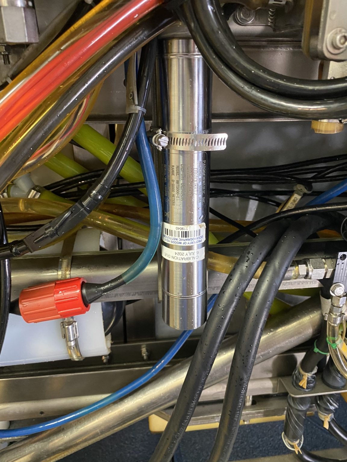
Alvin is equipped with two Paroscientific pressure/depth transducers. Both are temperature-compensated, precision quartz transducers, mounted symmetrically on the submersible (one on the port and starboard side of the vehicle at the same height and distance from the vehicle center of gravity). Measured external ambient hydrostatic pressure is used to calculate vehicle depth. The resultant depth data is displayed to the observers on the in-hull tablets in the Metadata section of the imaging system and Sealog interfaces. This information is also available to the pilot on the primary command and control screen and on the "Sensors" page of the C&C software. Depth transducers are routinely calibrated by the manufacturer (typically on a 24-month cycle).
Read more
Note: A digital readout for the starboard depth sensor is available to the pilot on the port side of the personnel sphere. This is a redundant gauge that does not utilize the Fofonoff algorithm to convert pressure to depth and is therefore more conservative and less accurate. Users are directed to ignore this readout.
| Sensor resolution: | 0.1 meter |
The Alvin command and control software logs calculated depth in meters and external hydrostatic pressure (PSI). Local parameters (salinity, temperature, latitude corrections) combined with raw pressure may be used to calculate depth (user post-processing).
Pressure conversion is based on: "Algorithms for Computation of Fundamental Properties of Seawater", by N.P. Fofonoff and R.C. Millard Jr. This algorithm assumes a latitude of 30 degrees, a salinity of 35 ppt, and a temperature of 0°C. According to this publication, "the correction for the actual density distribution would be 2 meters or less".
The following table can be used to refine the observed and logged depth by applying a correction for the actual latitude of the dive.
| Depth (m) | ||||||
|---|---|---|---|---|---|---|
| 1000 | 2000 | 3000 | 4000 | 5000 | ||
| Latitude | 0 | 1.3 | 2.6 | 4.0 | 5.3 | 5.9 |
| 10 | 1.2 | 2.3 | 3.5 | 4.6 | 5.2 | |
| 20 | 0.7 | 1.4 | 2.1 | 2.8 | 3.2 | |
| 30 | 0.0 | 0.0 | 0.0 | 0.0 | 0.0 | |
| 40 | -0.9 | -1.7 | -2.6 | -3.4 | -3.9 | |
| 50 | -1.8 | -3.6 | -5.3 | -7.1 | -8.0 | |
| 60 | -2.6 | -5.3 | -7.9 | -10.6 | -11.9 | |
| 70 | -3.3 | -6.7 | -10.0 | -13.4 | -15.0 | |
Trim
The trim system allows the pitch angle of the submersible to be adjusted by pumping as much as 500 pounds of ballast between tanks located in the bow and stern. Normally, this system is used to maintain a level attitude as the load in the science basket varies during a dive, but it also permits the submersible to intentionally pitch bow up or bow down.
Variable Ballast
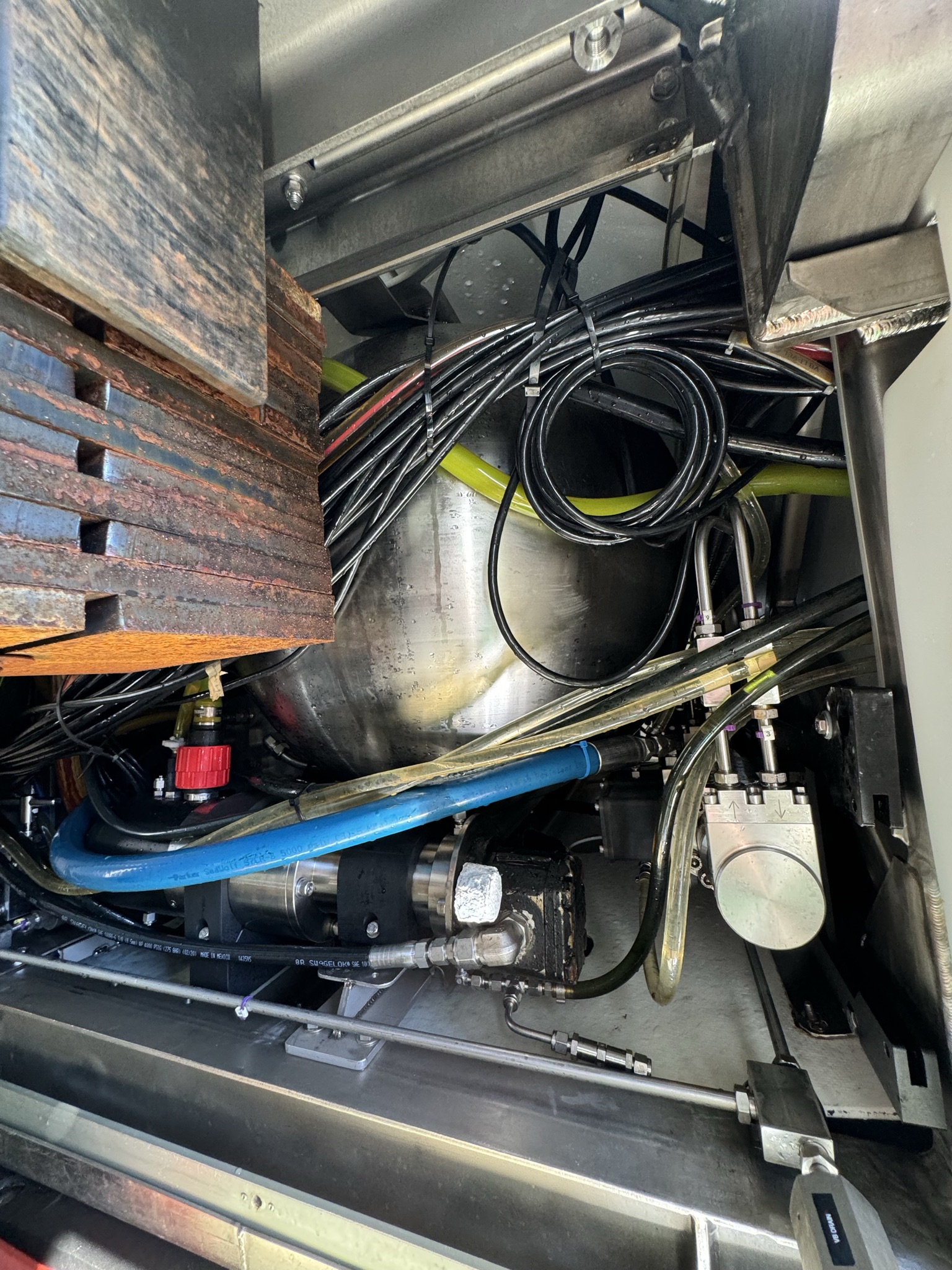
The variable ballast (VB) system is a fixed displacement, variable mass system that allows the Pilot to adjust the buoyancy of the submersible while at depth in order to achieve neutral, negative or positive trim, as well as provide reserve buoyancy for sampling payloads depending on the mission requirement at the time.
Read more
Salt water is added or removed from spherical titanium ballast tanks to effect a weight change of up to 10 pounds per minute. This system can be used to neutralize the submersible's rate of vertical motion, thus allowing it to hover in the vicinity of a cliff or underwater structure.
Vertical travel may then be accomplished using the lift thrusters. For routine, near-bottom transits, the submersible is ballasted to be near neutral buoyancy. In cases where the bottom consists of light sediment, the Pilot may ballast about 10 pounds "light", thus allowing the vertical thrusters to be consistently used in a manner which directs their water jets upwards. To prevent drift caused by currents, the Pilot may use the variable ballast system to get 50 to 100 pounds heavy. The amount of variable ballast weight available on each dive is not a fixed number and is affected by the payload on the dive. With advance notice, the ballast system can be configured to provide as much as 500 pounds of variable ballast. An additional negative force of up to 300 pounds can be applied by downward thrust of the lift thrusters for short periods of time. The VB system is both power- and time-consuming, and numerous trim changes will reduce bottom "work" time.
The system consists of two subsystems: a seawater portion and an auxiliary hydraulic control portion. The seawater system directs and controls seawater flow and consists of three titanium spheres, a saltwater pump, one hydraulically-operated isolation valve, a flow control valve, a hydraulically-operated directional control valve, a system relief valve, two manual isolation valves, and interconnect tubing. The auxiliary hydraulic system operates the Pilot-actuated seawater isolation valves and directional control valve.
The system is not utilized for any safety-related functions, so its failure will not compromise the vehicle's ability to return to the surface and be recovered.
Sampling Equipment
Biological Sample Collection Boxes (Bio Boxes)
Alvin's standard biological sample boxes are constructed of 1" thick HDPE plastic and have a fully-hinged lid with a polyurethane tube seal. These boxes provide a reasonable measure of insulation and sample integrity. They are best used for robust samples as some mixing may occur during transit.
Standard Bio Box
12" x 12" x 24", 2 available, 5 lbs weight in water, 138 lbs full of water. Can be half-sectioned via a removable central divider.
Read more
Sensitive Sample Bio Box
Alvin's sensitive sample bio box is constructed of 1" thick black HDPE plastic and has a fully-hinged latching lid and a highly effective watertight seal. This bio box is purpose-built for sensitive samples that require a high degree of insulation and sample integrity. This box is reserved for sensitive samples and is not intended for general use.
12" x 12" x 18", 1 available, 5 lbs weight in water, 117 lbs full of water
CTD
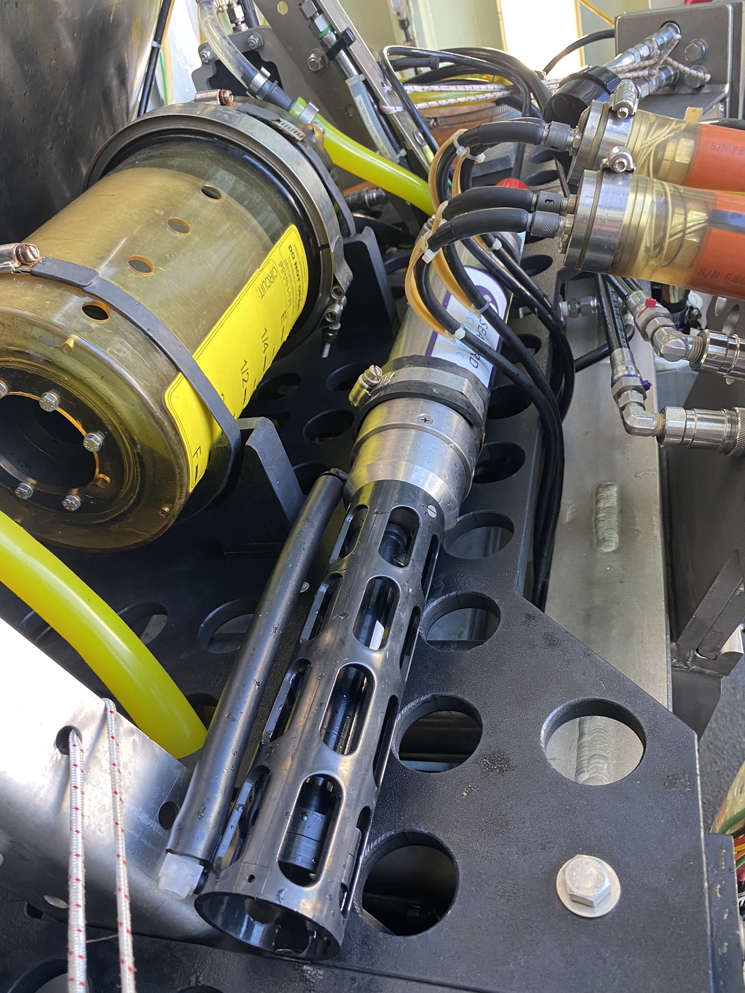
The SeaBird SBE49 profiling CTD measures conductivity, temperature, and depth (pressure) at 16 Hz (16 samples/second) as it travels through the water column. It features pumped and ducted constant flow for matched temperature and conductivity response, and measurements are made on the same sample of water with a predictable delay and predictable flow effects. CTD data can be used to calculate salinity, density, sound velocity, as well as other parameters of interest. The interface is RS-232.
Heat Flow Probe
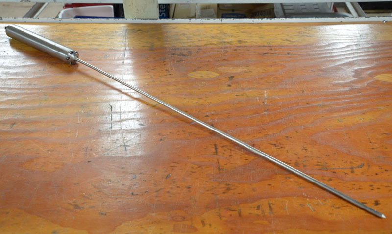
Alvin has a 0.6-meter long, five-element temperature sensor. This is used to measure temperature gradients when inserted into soft sediments. Measurable temperature range is 0 to 40 °C, with 0.2 degree accuracy and .001 degree resolution. Additionally, a temperature pulse can be generated and monitored to observe temperature decay in sediments. Data from the heat flow probe is normally displayed on the observer's internal video overlays and is additionally recorded in the submersible's computer data files. Water weight is 4 lbs, and basket space is required to carry the unit and quiver.
Magnetometer
Honeywell Magnetometer
This is a 3-axis magnetometer based on the Honeywell HMR2300 sensor. It is capable of measuring up to ±2 Gauss with <70µGauss resolution, at about 10 samples per second. Absolute accuracy is expected near 5000 µGauss. This instrument is commonly mounted on the starboard aft side of the science basket.
Major Water Samplers
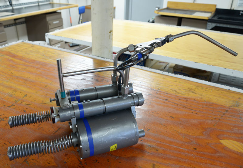
These 760 ml syringe-style instruments have inert titanium housings with an inductively-coupled link (ICL) for in situ temperature measurements, and are capable of handling water temperatures in excess of 400°C. They are typically configured in pairs on Alvin, but can also be configured and triggered individually. Single unit configuration does not support in situ temperature measurements. A total of six major pairs are available at any one time and require a dedicated mounting frame on the science basket. Water weight is 25 lbs/pair with ICL, 28 lbs full of water. Post-dive and post-cruise care and maintenance of this equipment is the responsibility of the science party.
Niskin Bottles
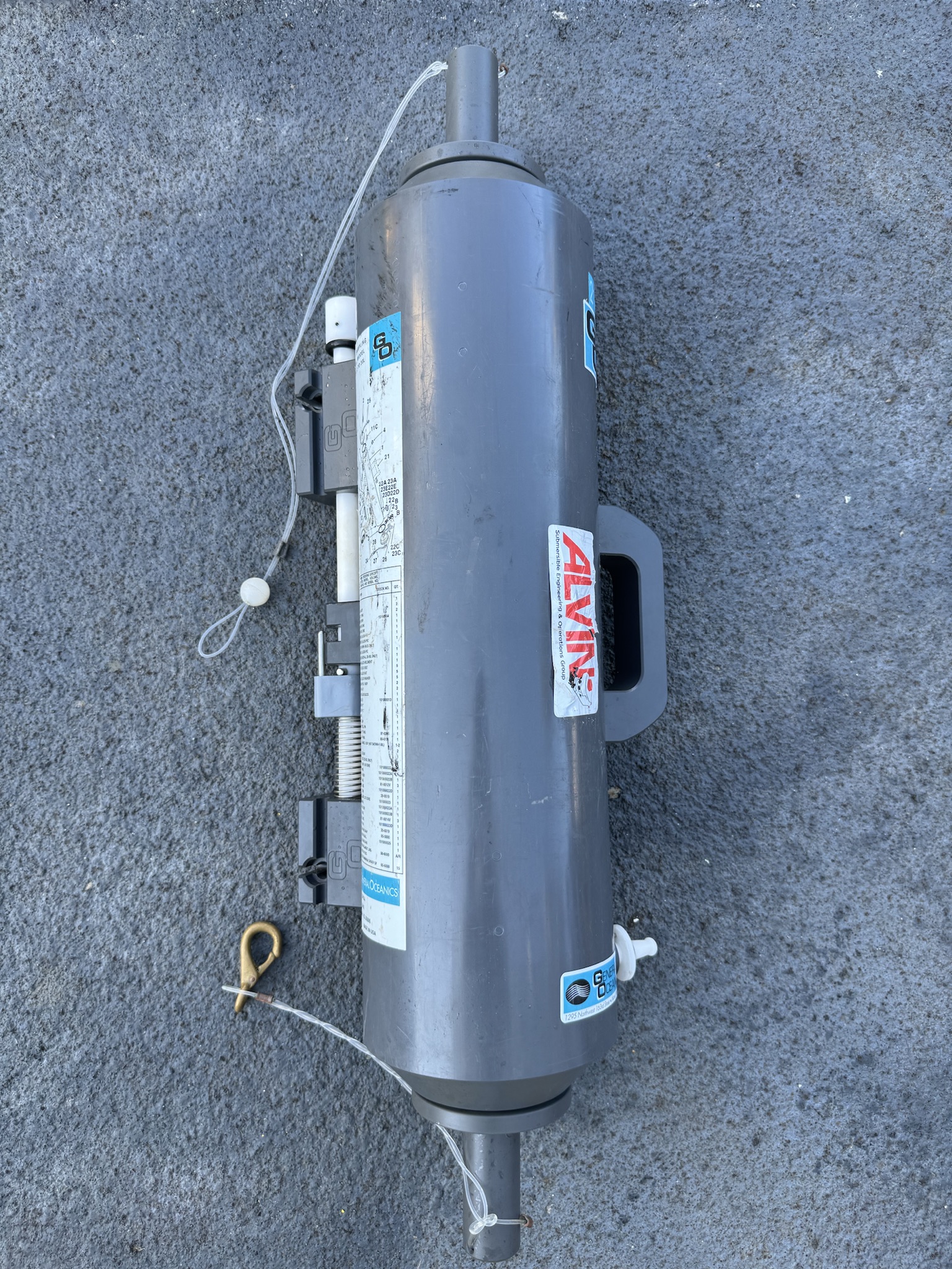
These instruments are commonly used to capture water column and hydrothermal vent plume water samples. They seal off the sample and allow it to be brought to the surface without mixing with water from different depths. The water collected by Niskin bottles is used for studying plankton or measuring many physical characteristics such as salinity, dissolved oxygen, nutrient concentrations (such as phosphate, nitrate and nitrite), and dissolved organic and inorganic carbon.
1.2-liter PVC Niskin bottles mounted in a 5-pack arrangement are standard and can be triggered individually by the manipulator. The rack is easily removed post-dive for science processing. Water weight is 15 lbs, 41 lbs full of water. Overall basket space required is 12" x 18".
Two individual 5-liter Niskin bottles are also available, with water weight 6 lbs or 18 lbs full of water.
Push Corers
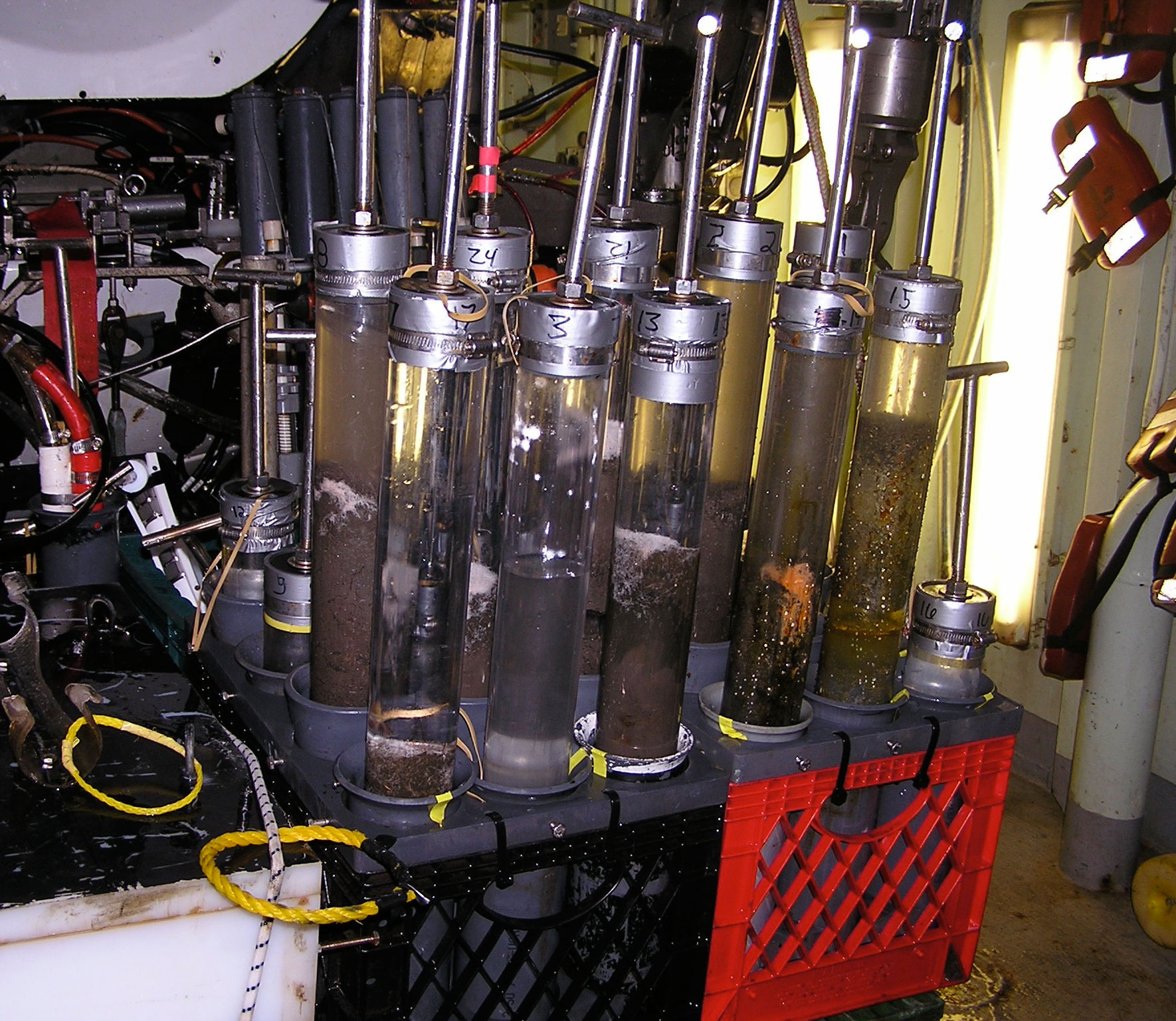
Push corers are soft sediment samplers deployed using a manipulator. They are 2.5" ID by 12" long, utilizing a removable, clear polycarbonate barrel. Commonly stowed in either a 3x3 or 3x4 rack for a total of 9 or 12 corers, respectively. Alvin can carry two of these racks for a maximum of 24 corers per dive. Note that carrying this many corers will limit the basket space available for additional science equipment. A total of 48 push corers can be carried if investigators supply another 24 and there are no other basket space requirements. The racks are easily removable for post-dive processing.
Read more
There are a limited number of core barrels available during any particular leg. Investigators contemplating keeping samples in a collection barrel for post-cruise examination must make arrangements to replace all barrels used. PIs should also be prepared to supply watertight plastic end caps for any samples taken. Procurement information for these two items can be furnished upon request. Water weight per 3x4 rack is 36 lbs, 48 lbs full of water. Overall basket space required is 12"x18" per rack.
Rock Collection Baskets
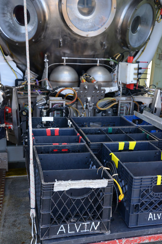
Alvin can be equipped with milk crates fastened to the science basket in order to transport rocks or other bulky items collected using a manipulator. If desired, the milk crates can be divided in order to help distinguish rocks taken from multiple sites.
Equipment available:
- 13" x 13" x 11" milk crates
- 13" x 19" x 11" milk crates
- Dedicated 3' x 4' wire basket with sections
Scoop Nets
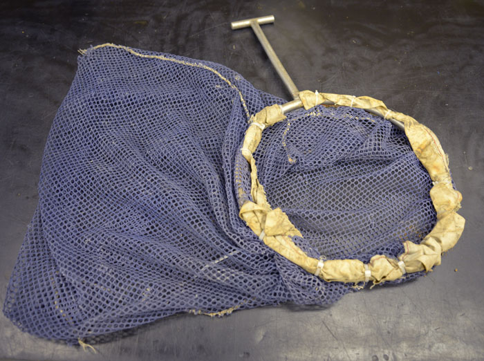
A number of manipulator-deployed scoop sample nets are available in various shapes and sizes. Typically these are rigged with an open 1/4" mesh bag or canvas rock bag and placed in the science basket on a space available basis. Water weight is 2 lbs each.
Slurp Samplers
The slurp samplers consist of a collection chamber and a hydraulically powered water pump. A nozzle with a tube connected to it is held and moved by a manipulator while water is pulled into the nozzle by the pump. The water travels down the tube into the collection chamber, and then goes through a mesh screen before going through the pump itself. Biological samples are sucked into the nozzle and deposited in the collection chamber. They are kept from going into the pump by the mesh screen. The screen can be changed for coarser or finer mesh as needed. Two styles of collection chamber are available; single chamber and 5-chamber.
Read more
Single chamber: a large cylindrical single collection chamber into which all samples will be deposited. Water weight 2 lbs, 27 lbs full of water.
5-chamber: five separate cylindrical collection chambers of 4.5 inch ID x 11.5 inch height. One chamber is used at a time and the chambers are rotated by a hydraulic actuator mounted to the bottom of the 5-chamber assembly. Water weight 10 lbs, 140 lbs full of water.
Temperature Probes
RTD
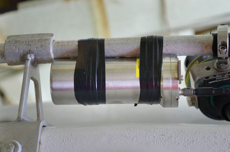
The resistance temperature device (RTD) is capable of measuring water temperature up to 400°C, reporting about one sample per second. The instrument provides 0.01°C resolution and accuracy is 0.02°C. Typical sensor tips are 1/4" diameter and 12" long. Sensors are manipulator deployable utilizing a T-handle. Temperature can typically be reported from several sensors at once.
Read more
ICL
The inductively-coupled link (ICL) temperature probe is a wireless data transfer device most commonly used in conjunction with major water samplers to take real time temperature measurements during sampling. The ICL electronics can also be used for a variety of other data transfer and control functions. The sensor tip of the ICL probe is installed in the inner bore of the water sampler intake nozzle and senses the fluid temperatures as water flows past. The measurable temperature range of the probe is 0 to 450°C. Data from the probe is normally displayed on the observer's internal video overlays and is additionally recorded in the submersible's computer data files. Water weight (ICL probe only) is 1 lb.
This system is currently only rated for use on dives to a maximum depth of 4,500 meters. A replacement system that is rated to 6,500 meters is under development.


